The KVAR Power Factor Optimizer from Save Energy LLC is a typical example of this scam. Others to look out for are KVAR Energy Saving Systems, KVAR EC, KVAR Energy Contoller KEC PU1200, Nevvus Powerguard, Power-Save 1200, Power Saver HOME, Kilowatt Nanny, PowerwoRx-e3, Power Saver Enersonic and SurgeXpro."
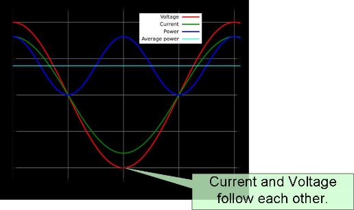
The power factor of a toaster or ordinary incandescent light bulb is 1 (one). Devices with coils or capacitors (like pumps, fans and florescent light bulb ballasts) have power factors less than one. When the power factor is less than 1, the current and voltage are out of phase. This because extra energy is being stored and released into the inductor (motor coil) or capacitor on every AC cycle (usually 50 or 60 times per second). Graphically, the voltage and current used by your toaster would looks like this.
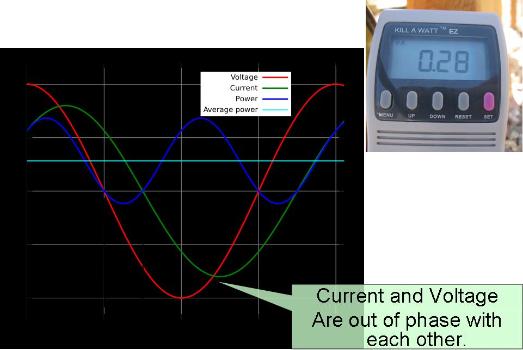
The meter below is measuring the power factor of a small aquarium pump, and is showing a power factor of 0.28. If you were to graph the voltage and current used by the pump, you would see that the red and green lines (the voltage and current) are shifted relative to each other compared to the graph above, like this:
This isn't a problem for the motor - in fact it is a natural part of its operation. It is a problem for the electric utility company because customers are charged for kWh (true power - the work the motor does) which is oblivious to the extra current due to the "reactive power" which is being stored and released by the motors coils. If an industrial customer has a low power factor and draws more current and therefore requires thicker wiring to the plant, larger utility power transformers and more energy is lost as heat in the wires due to the extra current - then the electric utility company has the right to charge more for providing this larger equipment.
Residential customers are not penalized for having a low power factor. You will not save a single cent by using these devices in the home. It will not help your washing machine run better. The power factor is not on your utility bill. While power factor correction is valid for many industrial customers who use large amounts of power, it is a deception when marketed to home owners as a way to save money on their electric bill.
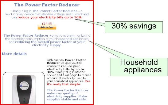
Here is another one that is being marketed to households:
For a more comprehensive review of the subject, go to Wikipedia - Power Factor Correction.
This article is excellent: Lessons In Electric Circuits -- Volume II Power Factor
Update: December 2008 -- The issue of I2R losses has been coming up, so I will address it below:
Energy Loss due to low power factor heating wires in a residence
Here are the assumptions:
- Residential power meters measure real power. The oscillating power (the reactive component) that is generated by inductive motors travels through the wires between the motor and the utility grid, passing back and forth through the residential meter.
- Capacitors can be used to intercept the reactive power from inductive motors, and return it to the source on the next cycle. However, if the capacitors are at the service entrance or utility panel, they will do nothing to reduce I2R losses in the wiring between the panel and the motor. In order to eliminate line losses, the power factor correction device must be mounted at the inductive load.
- Not only must it be installed at the load, it must be switched with the load. If it ends up absorbing reactive power from a refrigerator, AC unit or other motor while the machine it is connected to is not in use, it defeats the purpose of connecting it close to the load.
- If the resistance of the wiring was zero, then the power losses due to the reactive components would also be zero. However, residential wire does have a resistance as we will calculate below.
- Ignore the fill cycle since its power consumption is 200 time smaller than the wash and spin cycles.
- Lump the wash and spin together since they both use a similar amount of energy (another reason to get a front loader. They use about 22 watts on the wash cycle because they don't have to slosh around gallons of water). We will be conservative and use the worst numbers, those of the spin cycle:
- 30 minutes
- Power Factor: 0.47
- Current: 8.94A
- Real power: 513W
- Apparent power: 1081VA
- The distance between the machine and the panel is 40 feet. I think that is generous in most cases.
- 110V machines are usually wired with 14AWG copper. Looking on the net, we can find some values:
- The unit must be installed at the source, not the panel or we defeat the purpose of eliminating the I2R losses.
- We will use an interest rate of 7%, the inflation adjusted average growth of the stock market over the last 200 years.
- Life of capacitors is 15 years. After this, you will discard the power factor unit, or perhaps it will just become useless.
- AC Line filtering right at the meter (removes aliasing, important for very high Harmonic distortion loads, such as a load with lots of PC's)
- AC couples Line and Neutral, so large transient voltages on the Line are not seen by the meter chip (become "common mode")(kind of like PSRR / CMRR system spec, (remember meter only increments)
- Filtering out-of-band AC signals, Broadband PLC modems, Narrowband PLC modems, X10 signals.
Now for some tests (using test equipment) with a top fill washing machine on a regular cycle:
Make Whirlpool
Model LCR7244JQ3
Rated 9.8A 120 Volts
Age: 3 years
Fill cycle:
Real power: 3W
Current: 0.4A
Voltage: 121.3VAC
Apparent power: 5VA
Power factor: 0.68
Length of fill 5 min
Wash cycle:
Real power 630W
Current: 9.54A
Voltage: 120.2 VAC
Apparent power: 1144VA
Power factor: 0.53
Length of wash: 25 minutes
Finally the spin cycle while water still draining:
Real power: 689W
Current: 9.11A
Apparent power: 1106VA
Power factor: 0.58
Spin when it gets up to full speed:
Real power 513W
Current 8.94A
Apparent power: 1081VA
Power factor: 0.47
The complete cycle took 41 minutes. Total real energy used (the part we pay for) 0.23 kWh.
From the data above, we can do the following:
That leaves us with:
From this we can calculate the following:
Impendence phase angle is arcos(True power / apparent power) = 62 degrees
Reactive power = Real power * atan(phase angle) = 423 VAR
The above is easier to conceptualize as a power triangle, a right angle triangle where the apparent power is the hypotenuse, and the other two sides are the reactive and real powers. The reactive part does not do work. The real part only does work. The apparent power is what you get when you measure the voltage and current as measured with a meter.
Now, we will assume that 513W of real work can wash and spin the clothes. Had the power factor been 1, we would have needed 513W/110V = 4.66A. However, because of the poor power factor, we drew an extra (8.94 - 4.66) = 4.27A
Stage Two:
We need to calculate the energy loss between the washing machine and the service panel. Lets assume the following:
2.524 Ohms/1000 feet http://www.mwswire.com/barecu5.htm
2.525 Ohms/1000 feet http://en.wikipedia.org/wiki/American_wire_gauge
2.6 Ohms/1000 feet http://www.engineersedge.com/copper_wire.htm
Let's take the highest value. Using this, we can calculate the resistance of a 40 length of wire to be 40ft * (2.6Ohms/1000ft) = 0.104 Ohm.
There are also connections, a screw clamp on the circuit breaker, possible a few spring connectors if the wall boxes are daisy chained, and a screw connection on the wall plug. So lets calculate it directly. When the washer moved from fill to wash, the voltage dropped (121.3 - 120.2) = 1.1 volts. This occurred at a load increase of 9.41A. V = I/R so R = V/I = 1.1v/9.41 = 0.11 Ohms. The washer above is located on the 3rd floor, the breaker panel is on the garage.
So, it appears that both methods of calculation give us similar results for resistance. Let's use the higher value, 0.11 Ohms.
Stage Three:
We want to know the energy loss by heating the wires between the washing machine and the utility power meter. We really don't care what happens on the other side of the meter, although the power company does.
Power = I2R = 4.27A * 4.27A * 0.11Ohms = 2 Watts.
Energy = (2W/(1000W/Kwh)) * 1/2 hour = 0.001 kWh
Cost of this power: 0.001 * 12 cents/kWh = 0.012 of a penny
Finally, lets assume you run a wash every day of the year (perhaps true if you have children). Annual power cost: $0.00438
Stage Four - the Economics:
Let's calculate the present value of a hypothetical power saving device:
PV(7%,15years,$0.00438) = $0.04
Provided that MS Excel's PV calculation is still accurate with fractional cents, it looks like the investment (priced at approximately $400 for a 1200W unit) is worth only 4 cents.
Maybe.
I live in a very cold climate and heat with electricity because natural gas it not available and trees are scarce. All the wiring in the house aside from exterior lighting, is in heated spaces. Most of the year, the "wasted heat" is actually useful.
Had the correction unit been placed at the panel (e.g. a whole house model), the power savings would have been zero. Absolutely zero. That is why advertisements like the following from PowerwoRx should be considered a fraud:

The following is from ENERGYSTAR. This statement is no longer to be found now that they have reorganized their website, however, there is an archived copy here.
Do Power Factor Correction Devices (sometimes called Amp Reduction Units or KVAR) really save money? Can they earn the ENERGY STAR label?
ENERGY STAR does not qualify any Power Factor Correction Devices. Please send us an email at logomisuse@energystar.gov if you see one that claims to be ENERGY STAR certified.
Power Factor Correction Devices claim to reduce residential energy bills and to prolong the productive life cycles of motors and appliances by reducing the reactive power (kVAR) that is needed from the electric utility.
We have not seen any data that proves these types of products for residential use accomplish what they claim. Power factor correction devices improve power quality but do not generally improve energy efficiency (meaning they won't reduce your energy bill). There are several reasons why their energy efficiency claims could be exaggerated. First, residential customers are not charged for KVA-hour usage, but by kilowatt-hour usage. This means that any savings in energy demand will not directly result in lowering a residential user's utility bill. Second, the only potential for real power savings would occur if the product were only put in the circuit while a reactive load (such as a motor) were running, and taken out of the circuit when the motor is not running. This is impractical, given that there are several motors in a typical home that can come on at any time (refrigerator, air conditioner, HVAC blower, vacuum cleaner, etc.), but the unit itself is intended for permanent, unattended connection near the house breaker panel.
For commercial facilities, power factor correction will rarely be cost-effective based on energy savings alone. The bulk of cost savings power factor correction can offer is in the form of avoided utility charges for low power factor. Energy savings are usually below 1% and always below 3% of load, the higher percentage occurring where motors are a large fraction of the overall load of a facility. Energy savings alone do not make an installation cost effective.
End of Quote
Still not convinced?
One of the more surprising comments I have received lately was that this kind of analysis is "Rubbish" or that it doesn't address the "fact" that some acquaintance of theirs is saving money using a power factor correction device. This is unfortunate. I don't dispute that you may have seen a reduced power bill, just the "fact" that this reduction is due to the "device" and not other factors that were overlooked.
Electrical theory is not some "theory" that might or might not be true. This is an area that has been well understood for more than a century and concepts like resistance, impendence and reactive current are accepted as reality -- something which you ignore at your peril. Even if future understandings of particle physics were to give us new insights to old laws -- these old laws are for all practical purposes, perfect for predicting an outcome in household situations.
Despite this, people install devices like this and become convinced that any reduction in their power bill is due to the device. Remember that if you want to test something like this with the intention of proving that it defies our current engineering knowledge, you are going to have to use calibrated test equipment and carry out carefully controlled experiments. The temperature (degree days) vary greatly from year to year, habits change (longer or shorter showers) and a host of other things will vary your monthly power bills significantly from any chosen month from one year to the next. Even thinking about your energy saving device causes behavior changes -- like turning off lights when you leave a room, running the water less, etc. Therefore, your monthly power bill is in no way a controlled experiment, and the savings you are hoping to measure are very small compared to regular variations. Comparing power bills is useful, but only verifies significant savings such as switching from electricity to natural gas, changing high flow to low flow shower heads or other major changes.
If your experiments lead you to conclude that you actually save significant percentages of power using one of these devices, you need to re-evaluate your controls. Since these results would be violating the laws of physics, nobody will believe them unless they can repeat them. If nobody can duplicate your results (which is extremely likely) then you must re-evaluate your experiment. Finally, very few people who can set up a proper experiment are going to be willing to spend their hard earned money to purchase a device and then spend time conducting an experiment to prove that their purchase was a waste of money. And even if they did, would you believe them?
-- January 2009 --
I will post any feedback received below. I have left out names and e-mail addresses (unless the authors request it) so that they don't get spammed.
Great analysis, Peter. Particularly your point about connecting the power factor correction capacitor(s) directly across the inductive motor so that they are only in the circuit when the motor is switched on. Now, multiply that exercise for every inductive motor in the home -the compressor motors for the ac and the refrigerator(s), dishwasher, hot water circulating pump(s), etc. Every one of these appliances needs its own capacitor. It thus becomes obvious why these devices are not even remotely cost effective for residential applications. And certainly not in the way the manufacturers recommend that they be installed, that is, permanently connecting them at the main panel. Doing that drags the power factor capacitive when the inductive motors are off and could create some real problems with ringing voltages.
Peter, Thank you so much for your article on the PFC devices. I have been an electrician for 30 years and worked for electrical engineering firms for 10 of those years, specializing in power quality and diagnostic testing. I was researching for a friend as I've run across these PFC scams before. I passed your link on to him and he just saved a lot of money by not being duped. Very well done! -- Mike Cole
First let me say that your article on power factor is the best I have found. Second, I am an electrical engineer - electronics not power - but I do remember power factor calculations from Freshman circuit theory. I agree and am convinced that as an energy consumer geting one of these KVAR units is a waste of money but I was wondering if they might be useful as an energy producer. In other words we know that power companies do save money by power factor correction in their distribution grid. Since I am now a very small power producer with my PV system can a KVAR unit help me improve the delivery of the power that I am producing? I expect the answer is no but I have not found this specific question answered anywhere yet. -- Burt Wagner
Hello Burt,
The answer is yes. There are a few situations where it might help you. Power companies have to use larger diameter wiring and bigger transformers to carry the reactive power, so they encourage factories with low power factors to improve it by demanding penalties. This reduces their infrastructure costs.
You PV system has similar issues. You inverter is very expensive and is rated in VA (volt amps). The same goes for a computer uninterruptable power supply. A Tripplite brand 1200W UPS is rated as 1500VA. The 1500VA is the real limit. The 1200W assumes a 0.80 power factor. If you were plugging in a toaster instead, it could support 1500W.
So, if you connect a large power factor correction unit to your PV systems inverter, you would do the following: 1) accomplish nothing in terms of resistive losses -- for that you would have had to connect the PF correction directly to things like the washing machine 2) reduce the size of the inverter required. The latter is analogous to what the power company sees -- increase the power factor close to 1.0, eliminate the reactive power and save money by reducing the size and capacity of equipment. For you, power delivery is about the batteries, cables to the inverter, inverter, charge controller etc. For them it is the size of wire on the poles and the size of the pole transformers, fuse capacities, size of utility poles to support the weight etc.
Even if the existing PV inverter is paid for, a power factor of 1.0 should allow it to run cooler and be less likely to overload when you have too many appliances on. You would probably want to get a PF meter and verify the real power factor. There are some cheap units for 100V that you can plug in the wall, but the best thing would be to borrow something like this: Extech Power Analyzer. If you have an expensive inverter, perhaps these measurements are built in.It might be difficult to prove if you would save money in premature inverter failures, but it would certainly be an interesting question to answer. Does a $3000 inverter run at half capacity last longer, perhaps it has internal fans that don't start up until it approaches 80% capacity etc.If you decide to experiment with this, please let me know how it works out.
Here is an analogy from Burt that is rather creative:Peter,
I did one more search on power factor correction and finally found a non-technical analogy that I can use to explain this whole thing to the person trying to sell it to me:
Think of a bag of potato chips.
You open the bag and it just doesn't seem full enough.
Then you look at the label and it says it's packaged by weight, not by volume.
Yes you only eat the chips. The extra air in the bag is not a scam. It's just an unavoidable and normal part of packaging and delivery.
The ratio of weight to volume would be like "power factor" of packaging and delivery.
Utility power is like that bag of potato chips.
"Real" power (watts) is like the chips. Real power is the only power your motor (or fridge, or hair dryer, or TV, or light fixture...) can "eat."
The "imaginary" or "reactive" power is just "air" in the wires, an unavoidable part of what it takes to deliver the watts.
Plugging something into a receptacle to reduce power factor is like "vacuum packing" the bag. You get more "chips" (watts) in the same size "bag" (volt-amps).
The most common device for "vacuum packing" power is a capacitor.
The most common thing that blows more air into the bag is a motor.
So connecting a capacitor in parallel with a motor helps deliver more chips per bag (watts per volt-amp) to that motor.
By getting rid of the air in the bag you do not save any money since you are only being charged for the chips!
BUT the power company does care about the air in the bags since the larger bags require larger "trucks" to deliver the bags.
What do you think? I think this just may convince him. -- Burt
comments = I just reviewed your article on Power Factor Correction. I agree with your conclusions BUT I think other factors might be resulting in the savings some people claim.
I would respectively suggest that all electricity meters are not measuring ONLY real power. The very old meters certainly tried to do this but with some newer electronic meters I'm not so sure.
The most popular E-Meter chips are from Analog Devices, one of the latest is the ADE7757. Notice that PF error is quoted as a spec for this chip but is not mentioned in earlier chips. However notice that Harmonic distortion is not a meter spec, nor is AC-Line Noise rejection.
http://www.analog.com/static/imported-files/application_notes/81462932AN679_a.pdf
http://www.analog.com/static/imported-files/tech_articles/17011149511795ANALOG_PAGE_68-71.pdf
Also notice that power is recorded as a pulse (usually optically isolated). This suggests that any unusual Power line condition that results in a reading error can only cause a meter Increment (there is NO Meter decrement function), so unlike old meters there is no way to make the meter run backwards. Even if you actually source power such as from a solar cell array.
OK so what are the PFC caps doing
BTW: although Analog Devices certainly knows what they are doing, many second tier semiconductor companies, that also try to do these meter chips, really don't have a clue, result all measurement errors are extra "real power" for the consumer
If my assumptions are correct than the correct system location for the PFC cap is directly across the meter, not at the load.
How can the measurement error occur:
Most E-meter's use an ADC (analog to digital converter) based on Audio Sigma Delta technology. If you want the power of the meter chip to be very low than you reduce the "over sample ratio" (If all signal content was at 50Hz (line freq) than in theory a second order sigma delta with a 10 times over samle ratio (sample frequency = 500Hz) would be adequate. Unfortunately 500Hz is only the 10th harmonic so a LOT of (switched mode power supplies) SMPS especially under light load, will consume a lot of their power at the 10th harmonic of the Line frequency (60Hz in the US), this could be completely misread by a low sampling frequency ADC.
For Narrow Band PLC (auto matic meter reading) the signal on the AC-line can be as high as 10Vp-p typically around 140Khz this is WAY out of band and needs to be removed before the ADC by an RC filter, many cheaper systems failed to use such a filter. As a result the Sigma Delta will often lock to this as some sort of "residual clock" remember these meter chips are typically a spin-off from Audio converters (In the case of Audio, aliasing to DC the residual Clock,from some cheap DAC, is a very good feature to have) In the case of a E-Meter chip it could mean a +-5% error.
Most of the problems I have mentioned would be significantly reduced by a nice big cap right across the E-meter, hence my assumption that this is in reality what the PFC caps are doing.
note: On re-reading the post I noticed that it seems to imply that Analog Devices is complicit in some sort of conspiracy against consumers, which I do not believe, at all.
Updates:
I have removed comments I had earlier from promoters of these scams because it became apparant that their arguments were adding nothing to the discussion and making this article more tedious to read. The arguments are always the same, namely a) my bills are lower, why don't you want to see them b) it's NASA approved c) recommended by the governments and universities but without links d) I don't know what I am talking about e) various promotional press releases and when that doesn't work, Ad hominem attacks.
I have contacted NASA for their opinion and position on the so called "NASA approved" claim, based on what looks like an old interoffice memorandum and will post their reply here when I get one.
I also encourage everyone to report these scams using the FTC so that they can track them. Unless many people complain, nothing will be done to crack down on types of scams. A good way to approach it is to quote the DOE/ENERGYSTAR site "We have not seen any data that proves these types of products for residential use accomplish what they claim. Power factor correction devices improve power quality but do not generally improve energy efficiency (meaning they won't reduce your energy bill)." and then point out that these people are claiming 25-30% savings for residential (not commercial) customers. Reviewers at the FTC will probably take the Environmental Protection Agency and Department of Energy as a trusted source even if they don't understand the technology. The gulf between the governmental source "they won't reduce your energy bill" and the scammer's "Save 30% on your electric bill" will be a clear indication of fraud worthy of investigation.
please keep sharing of knowledges with us.Thanks a lot for your great posting.
ReplyDeleteonline business listings